

Overview
Before you begin
Note: Before you begin, make sure you have read the manual beforehand.
Warning: The Bluetooth module is a board highly sensitive to electromagnetic fields. Therefore, you must be careful once it has been taken out of the safety cover so that the board does not get damaged due to electrostatic discharge.
Installing the Bluetooth module instead of the original GSM modem is a rather easy task; all you need to do is be careful and cautious.
The extraction of the telephone module from the middle panel is not part of this manual, as there are many guides on the internet.
Warning: If you do not have diagnostics at hand, then it is in your best interest to follow this rule when taking the PHM out of the car:
Before you disconnect the AC panel, take the keys out of the ignition and wait for approximately one minute. Do NOT put the keys back in the ignition before the panel is connected again.
If you do not do this, the airbag light will appear, which can only be deleted using diagnostics.
Equipment
Equipment you will need
You can see a list of what you will need for the replacement in Figure 1.1. Most of the parts are part of the package.
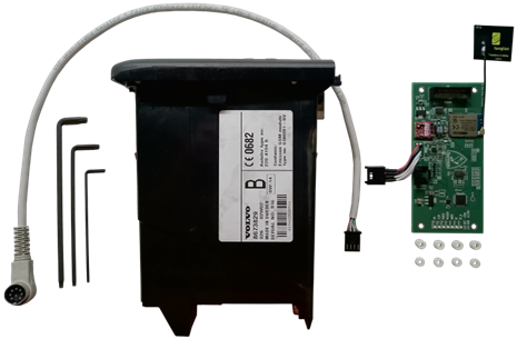
Figure 1.1
Equipment you will need that is not part of the package:
- Torx T6, T8, and T10
- The phone module (PHM)
What's inside the additional package
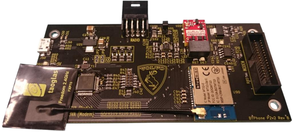
- The BT Phone P2v2 board + a Bluetooth antenna
- 4 pcs pillar bolts, height 1 mm, for both Ericsson and Wavecom modems
- 4 pcs pillar bolts, height 4 mm, for Ericsson modems
- Cable for connecting the BT module with the radio
Bluetooth Version
The Bluetooth version of the modem
The Bluetooth module can either be supplied with an external antenna, which is part of the package, or with an integrated one. Choosing between these is not an option.
Dismantling
Dismantling the GSM modem
Using the T10 Torx, unscrew the back connectors (Figure 2.1), and then use the T6 Torx to unscrew the 4 screws holding the front panel (Figures 2.2 and 2.3). While doing this, we advise you to have the phone module placed so that the buttons are pointing down.
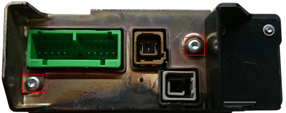
Figure 2.1
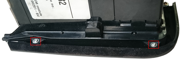
Figure 2.2
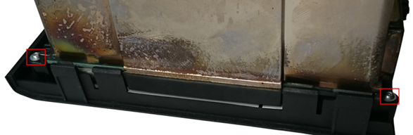
Figure 2.3
Proceed carefully after loosening the last screw so that the module does not turn over. Now remove the cover you have just unscrewed with caution, sliding it upwards.
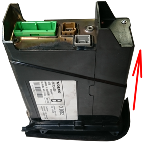
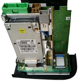
Figures 2.4 and 2.5
Carefully put the module on the table with the printed circuit board positioned horizontally (see Figure 2.6).
Warning: When placing it on the table, make sure the keyboard stays intact, as there is a SIM card slot within the front panel that is connected to the main board by a rather flexible cable that can break very easily.
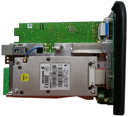
Figure 2.6
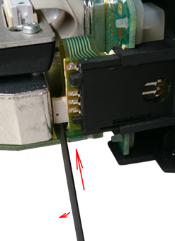
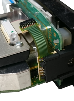
Disconnect the flat cable connecting the SIM slot with the main board. The easiest way to do this is to use the T6 Torx and slowly insert it between the main board and the connector (Figure 2.7). It is important that you choose a spot with no parts, ensuring the board does not get permanently damaged.
Figures 2.7 and 2.8
After disconnecting the connector (Figure 2.8), separate the keyboard (Figure 2.9). Again, watch out for the now disconnected connector, as it will most likely get in your way.
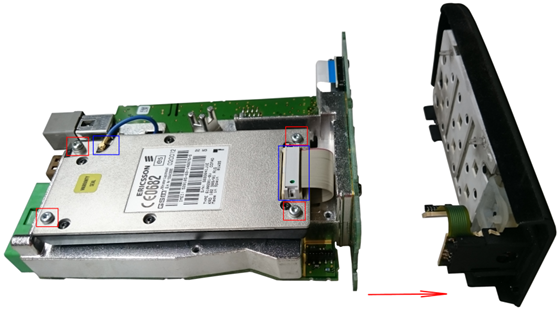
Figure 2.9
Disconnect the connectors highlighted in blue in Figure 2.9, and then use the T8 Torx to unscrew the 4 screws highlighted in red in Figure 2.9. Remove the GSM modem.
Installation
Installing the Bluetooth module
Place four 1 mm tall pillar bolts where the Bluetooth module will latch onto them (Figure 3.1).
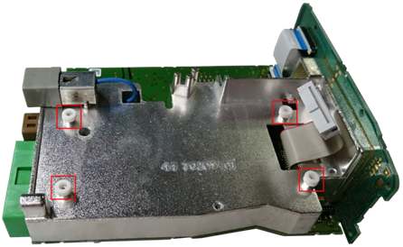
Figure 3.1
For Ericsson modems only
Place the 4 mm tall pillar bolts onto the original screws holding the GSM modem (Figure 3.2).
Follow-up for all modem types
Tighten the Bluetooth module using the original screws (Figure 3.2). Connect the central 30-pin connector (Figure 3.2, blue rectangle in the top right corner). The original connector for the GSM antenna must be placed into an entirely free space (Figure 3.2, blue rectangle in the top left corner) to avoid causing a short circuit by potentially falling freely onto the board.
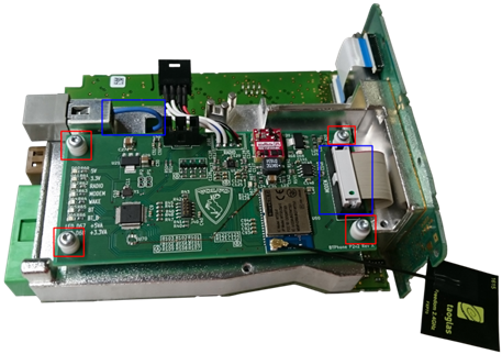
Figure 3.2
For Bluetooth modules with an external antenna only
Glue the antenna onto the telephone module. The ideal place for it is pictured in Figure 3.3. If you have disconnected the Bluetooth antenna connector while gluing, do not forget to connect it again.
Follow-up for all Bluetooth modules
Connect the keyboard back to the module (Figure 3.3).
Warning: Do NOT connect the SIM card connector back to the board. It might look like it is connected in Figure 3.3, but it is not. Leave the connector as it is so that it cannot cause any damage or a short circuit by falling freely.
Note: Newer firmware versions from 2018 and later will check this. If the connector is connected, there will be no damage, but certain functions will not work and a “SIM ERROR” sign will appear on the dashboard.
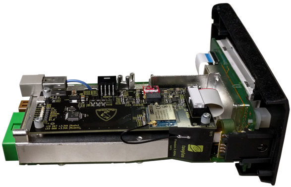
Figure 3.3
Covering Up
Covering up
Put the module back up, with the keyboard facing down. Place the cover back on the module (Figure 4.1) and tighten it with its original screws.
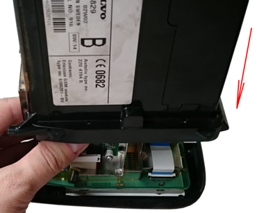
Figure 4.1
Lift the loosened part of the cover using the T6 Torx, unscrew the two highlighted screws (Figure 4.2), and separate it (Figure 4.3). This cover will no longer be needed and will enable access to the connector providing connection to the radio.
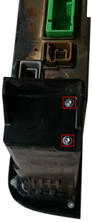
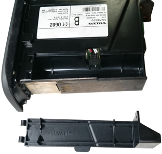
Figures 4.2 and 4.3
Connect the cable to the connector (Figure 4.4), and the installation is done.
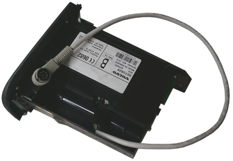
Figure 4.4
Now you may place the telephone module back in the car. Do not forget to connect the connector both to the radio and to this module.
Thank you for your purchase, and I wish you many beautiful moments with this modified module.
Final Takeaway
Installing the Bluetooth module instead of the original GSM modem is a rather easy task, but the module and connectors must be handled carefully. Before reinstalling the telephone module in the car, make sure the connector is connected both to the radio and to this module.