Přehled
Než začnete
Poznámka: Než začnete, ujistěte se, že jste si předem přečetli celý návod.
Varování: Bluetooth modul je deska velmi citlivá na elektromagnetická pole. Jakmile jej vyjmete z ochranného obalu, zacházejte s ním opatrně, aby nedošlo k poškození desky elektrostatickým výbojem.
Instalace Bluetooth modulu místo původního GSM modemu je poměrně jednoduchý úkon; je pouze potřeba postupovat pečlivě a opatrně.
Vyjmutí telefonního modulu ze středového panelu není součástí tohoto návodu, protože na internetu je k dispozici mnoho návodů.
Varování: Pokud nemáte po ruce diagnostiku, je ve vašem vlastním zájmu dodržet při vyjímání PHM z vozidla následující pravidlo:
Než odpojíte panel klimatizace, vytáhněte klíč ze zapalování a počkejte přibližně jednu minutu. NEVKLÁDEJTE klíč zpět do zapalování, dokud panel nebude znovu připojen.
Pokud tento postup nedodržíte, rozsvítí se kontrolka airbagu, kterou lze vymazat pouze pomocí diagnostiky.
Výbava
Co budete potřebovat
Seznam toho, co budete pro výměnu potřebovat, najdete na obrázku 1.1. Většina dílů je součástí balení.
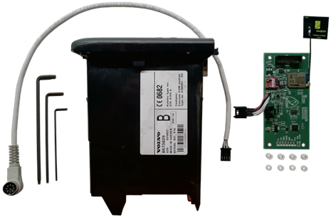
Obrázek 1.1
Výbava, kterou budete potřebovat a která není součástí balení:
- Torx T6, T8 a T10
- Telefonní modul (PHM)
Co je uvnitř doplňkového balení
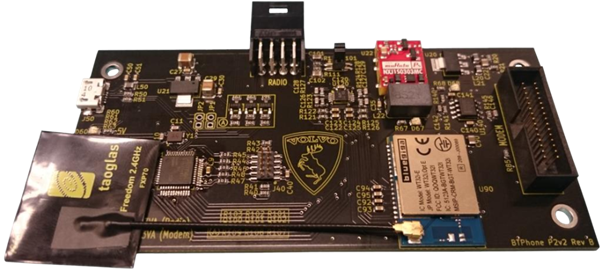
- Deska BT Phone P2v2 + Bluetooth anténa
- 4 ks distančních sloupků, výška 1 mm, pro modemy Ericsson i Wavecom
- 4 ks distančních sloupků, výška 4 mm, pro modemy Ericsson
- Kabel pro propojení BT modulu s rádiem
Verze Bluetooth
Bluetooth verze modemu
Bluetooth modul může být dodán buď s externí anténou, která je součástí balení, nebo s integrovanou anténou. Volba mezi těmito variantami není možná.
Demontáž
Demontáž GSM modemu
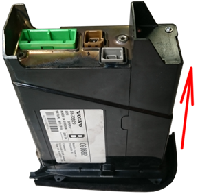
Pomocí Torxu T10 vyšroubujte zadní konektory (obrázek 2.1) a poté pomocí Torxu T6 vyšroubujte 4 šrouby držící přední panel (obrázky 2.2 a 2.3). Při tomto kroku doporučujeme mít telefonní modul položený tak, aby tlačítka směřovala dolů.
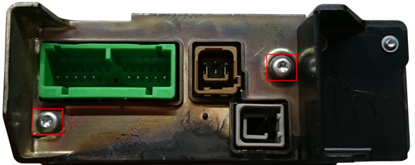
Obrázek 2.1
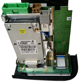
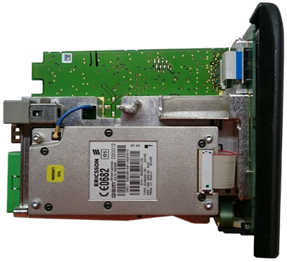
Obrázek 2.2
Obrázek 2.3
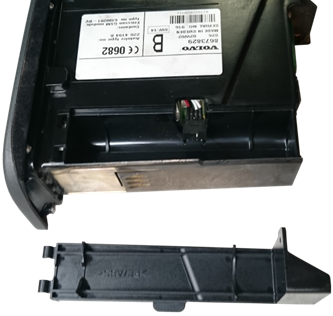
Po povolení posledního šroubu postupujte opatrně, aby se modul nepřevrátil. Nyní opatrně sejměte kryt, který jste právě odšroubovali, a vysuňte jej směrem nahoru.
Obrázky 2.4 a 2.5
Opatrně položte modul na stůl tak, aby byla deska plošných spojů ve vodorovné poloze (viz obrázek 2.6).
Varování: Při pokládání modulu na stůl se ujistěte, že klávesnice zůstane nepoškozená. V předním panelu se nachází slot pro SIM kartu, který je připojen k hlavní desce poměrně ohebným kabelem, jenž se může velmi snadno poškodit.
Obrázek 2.6
Odpojte plochý kabel spojující slot SIM karty s hlavní deskou. Nejjednodušší způsob je použít Torx T6 a pomalu jej zasunout mezi hlavní desku a konektor (obrázek 2.7). Je důležité zvolit místo, kde nejsou žádné součástky, aby nedošlo k trvalému poškození desky.
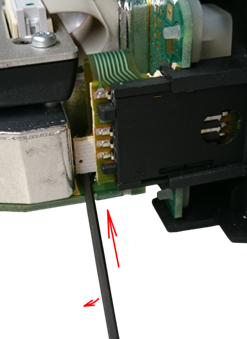
Obrázky 2.7 a 2.8
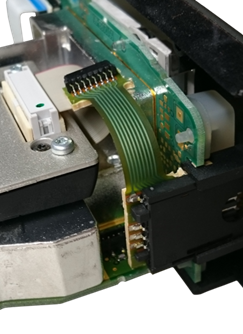
Po odpojení konektoru (obrázek 2.8) oddělte klávesnici (obrázek 2.9). Znovu dávejte pozor na nyní odpojený konektor, protože vám bude pravděpodobně překážet.
Obrázek 2.9
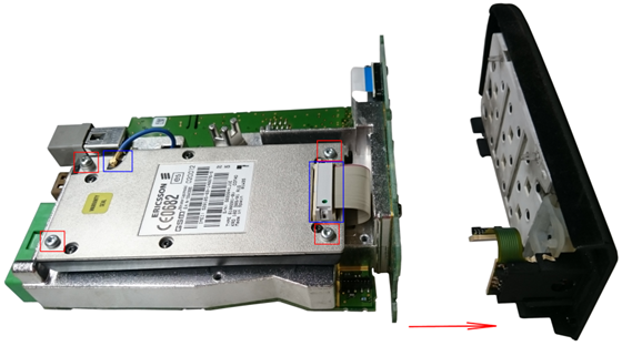
Odpojte konektory zvýrazněné modře na obrázku 2.9 a poté pomocí Torxu T8 vyšroubujte 4 šrouby zvýrazněné červeně na obrázku 2.9. Vyjměte GSM modem.
Instalace
Instalace Bluetooth modulu
Umístěte čtyři 1mm distanční sloupky na místa, do kterých se Bluetooth modul uchytí (obrázek 3.1).
Obrázek 3.1
Pouze pro modemy Ericsson
Umístěte 4mm distanční sloupky na původní šrouby držící GSM modem (obrázek 3.2).
Pokračování pro všechny typy modemů
Upevněte Bluetooth modul pomocí původních šroubů (obrázek 3.2). Připojte středový 30pinový konektor (obrázek 3.2, modrý obdélník vpravo nahoře). Původní konektor pro GSM anténu musí být umístěn do zcela volného prostoru (obrázek 3.2, modrý obdélník vlevo nahoře), aby nemohlo dojít ke zkratu při jeho případném volném pádu na desku.
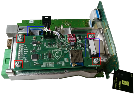
Obrázek 3.2
Pouze pro Bluetooth moduly s externí anténou
Přilepte anténu na telefonní modul. Ideální místo je zobrazeno na obrázku 3.3. Pokud jste při lepení odpojili konektor Bluetooth antény, nezapomeňte jej znovu připojit.
Pokračování pro všechny Bluetooth moduly
Připojte klávesnici zpět k modulu (obrázek 3.3).
Varování: NEPŘIPOJUJTE konektor SIM karty zpět k desce. Na obrázku 3.3 může vypadat, že je připojený, ale není. Nechte konektor tak, jak je, aby nemohl způsobit poškození nebo zkrat při volném pohybu.
Poznámka: Novější verze firmwaru z roku 2018 a novější toto kontrolují. Pokud bude konektor připojen, nedojde k poškození, ale některé funkce nebudou fungovat a na palubní desce se zobrazí hlášení „SIM ERROR“.
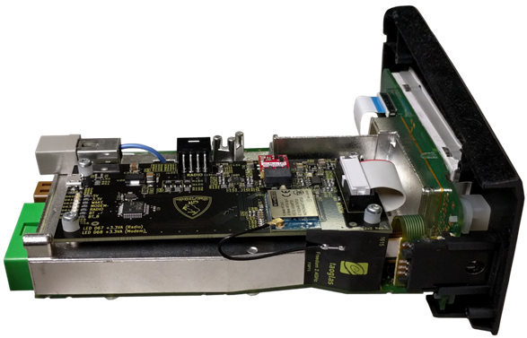
Obrázek 3.3
Zakrytování
Zakrytování
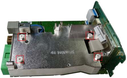
Postavte modul zpět tak, aby klávesnice směřovala dolů. Vraťte kryt zpět na modul (obrázek 4.1) a utáhněte jej původními šrouby.
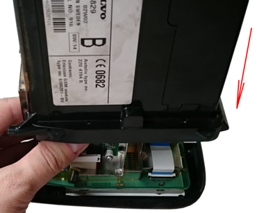
Obrázek 4.1
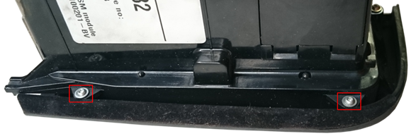
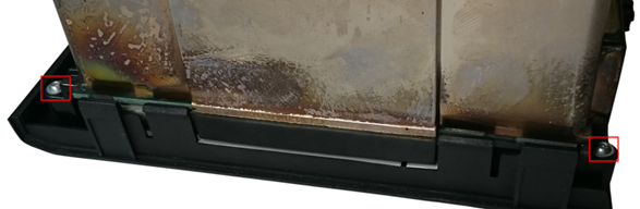
Nadzvedněte uvolněnou část krytu, pomocí Torxu T6 vyšroubujte dva zvýrazněné šrouby (obrázek 4.2) a kryt oddělte (obrázek 4.3). Tento kryt již nebude potřeba a umožní přístup ke konektoru zajišťujícímu propojení s rádiem.
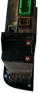
Obrázky 4.2 a 4.3
Připojte kabel ke konektoru (obrázek 4.4) a instalace je hotová.
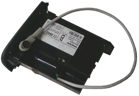
Obrázek 4.4
Nyní můžete telefonní modul vrátit zpět do vozidla. Nezapomeňte připojit konektor jak k rádiu, tak k tomuto modulu.
Děkujeme za nákup a přejeme vám mnoho příjemných chvil s tímto upraveným modulem.
Závěrečné shrnutí
Instalace Bluetooth modulu místo původního GSM modemu je poměrně jednoduchý úkon, ale s modulem a konektory je nutné zacházet opatrně. Před vrácením telefonního modulu do vozidla se ujistěte, že je konektor připojen jak k rádiu, tak k tomuto modulu.